Monday, March 28, 2011

Slightly larger, fullrange multimedia speakers

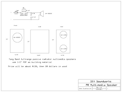
These are a simple passive radiator style bookshelf speaker.  They use Tang Band drivers and have an eight component frequency shaping filter.  If constructed with 1/2" MDF they should fit well on a desk, TV stand, or speaker stand.  These would be at home in any application where fairly low power are used and imaging is important. 
These speakers were designed on request from my friend Mike Pechy


Saturday, March 5, 2011

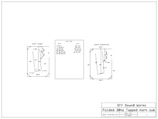
30hz Tapped horn, folded for a car

This is essentially the same sub as below, except it has only two drivers and will fit into a trunk very nicely.

Sunday, February 13, 2011

30Hz Tapped Horn, or A Really Big Subwoofer

Although its very large, and some of you may not think that 30hz is very low, this small footprint subwoofer will knock things off the walls of your home.  When placed in a corner, this subwoofer has an incredible efficiency.  Enough to keep up with any main speaker and will keep up with almost any system, even if only powered by 100 watts.  This subwoofer has an efficiency of 105db per watt, a maximum output of over 125db from 29hz up (when placed in a corner), and only takes up a spot on the floor that is 2ft wide and 18 inches deep.  The only downside is that it is 5' 8" tall.  However, if you have a room where your wife or girlfriend doesn't care about asthetics, then the height of this beast shouldn't matter.  This sub uses 4 Aurasound NS8-385-4A woofers loaded into a tapped horn designed using hornresp, downloadable here http://www.hornresp.net.ms/.  The woofers are available from Madisound at https://www.madisound.com/index.php.
I really only reccommend this sub to those who don't need output below 30hz, and to those with very efficient main speakers or like their music VERY loud.  This subwoofer will do very well with music as it can hit the lowest notes of bass guitars and pianos easily, and with incredible fidelity and ease.  I also reccommend a high order active crossover of 24 to 48 db per octave starting at any point below 90hz.

Frequency Response

Impulse Response

Aura NS8-385-4A
Diagram


I hope this explained it enough.  Also, This sub could be folded another time or a few more times so that it would be able to fit into a car.  Well, probably not a compact car, but an SUV.  Just ask in the comments and I'll put a double folded one up here.
Another thing I just thought of, it would be advantageous to put two of the woofers with the cone facing the opposite direction of the other two and wiring those two out of phase with the others.  This would help cancel out second harmonics caused by asymmetrical electromagnetic forces in the motors.  Some people claim that this has a huge effect while others don't seem to hear it, but if the magnet will fit the other way in the horn, then it should be a good thing to try.

Wednesday, February 9, 2011

2.1 Computer Speakers, or small room speakers

I have decided to design an inexpensive, easy to build, compact, subwoofer-satellite speaker system using passive crossovers and a small amplifier built into the subwoofer cabinet.  They use a single 3" driver per channel, and an 8" subwoofer to support the low end.  They are all in a sealed configuration for the simplicity of construction, and superior impulse response to ported designs.  These speakers have the capability to reach around 100 decibels, which is more than neccesary for computer speakers, which is a good thing, and all of this for $120 worth of parts, including an amplifier.  The only other cost is a sheet of 1/2" or 3/8" MDF, and a finish of your choice.  Which, depending on the finish, shouldn't cost very much, as the MDF will only be 12 to 15 dollars. 

Fullrange


Subwoofer
   The parts list for this particular project is fairly short and the construction is extremely simple, if you have a fair amount of common sense.  I am going to assume that if you are reading this and are seriously considering building one of these speakers that you know how to measure and cut wood so that the inside dimensions are as shown in the schematic picture, however, I love to help, so if there are any questions please leave a comment and I will address the issue right away.  But, after the construction of the three simple boxes, all that is left is to wire the crossover using your choice of board.  It works fairly well to solder the components together and then simply glue them with hot glue to something and place it inside the cabinet, or use one of the common circuit boards with many holes pre-drilled in it.  Those boards are available at Parts Express as well as Radioshack.   

suggested amplifier
 The amplifier for this project is only if you do not have one already and is of decent quality for a computer audio system.  The Crossovers for both the subwoofer and the satellites are located inside the subwoofer cabinet, therefore the amplifier should be connected directly to the subwoofer, then the crossover outputs on the subwoofer should be connected to the satellite speakers.  I think I covered everything you need to know to build these there. Now for some technical information.  The crossover between the sub and satellites is at 125hz, which is higher than optimal, but the best that can be done with such small drivers and still have decent output capability and distortion.  The reason for not having a tweeter on the satellites is because I believe it to be unneccesary with the driver used.  It has a frequency response that extends to 18khz, which is higher than most people over 20 can hear anyway.  But, if you feel the need for a tweeter, you simply will need to add two more parts to the crossover.  A capacitor on the tweeter as a highpass, and an inductor for the midwoofer as a lowpass.  The crossover should be fairly low, so between 3khz and 4.5khz would be good.  But some audiophiles believe that a point source loudspeaker has a property of musicality that is not found in multidriver speakers.  There is an L-Pad that should be placed in the satellite crossover circuit to balance the output between the subwoofer and the satellites (wiring diagram shown below).  The reason for this is that I designed the sub to have the same output as the satellites if placed under a desk, in the corner where your feet won't hit the cone, which puts it in 1 pi space.  Simply meaning that extra reflections from being so close to walls adds about 6db of output.  So if the subwoofer is used without being in a corner or under a desk you will need to attenuate the satellites slightly. Or if you prefer more bass.
How to wire an L-Pad
 The dimensions of the front of the satellites and the entire subwoofer cabinet are derived from the golden ratio of 1.618:1, which again, some audiophiles believe possess some unmeasurable property that makes the sound more musical.  But, the reason given for this increase in fidelity is that there is reduced resonance within the cabinet, reducing unwanted noise from vibrating cabinet walls.  which brings me to another point.  the satellites will be perfectly fine with 1/2" or 3/8" MDF, but if using the same thickness of material for the subwoofer cabinet it should be braced.  Simply cut strips of MDF about 2" wide and 7" long and glue them around the center of the cabinet, reducing the vibrations from the large front and rear panels. 


Parts List

Capacitors
2x47uF
2x4uF
2x0.22uF

Inductors
2x0.4mH air core
2x5.0mH steel core

Resistors
2x2.4 Ohm
2x7.0 Ohm
1x15W Stereo L-Pad

Others
2xTang Band W3-1053SC
1x Parts Express 299-094 8" subwoofer
1x stereo amplifier - Recommended Lepai Tripath TA2020 (Parts Express 310-300)
6x Red binding post
6x Black binding post
(or replace binding posts with 6x Terminal plates or cups)
Any question?  Please leave a comment if you do.


Monday, February 7, 2011

Dimensions, Schematic, and pictures of the design in the last post.

Ok, I seem to have lost the original schematic that used the same tweeter and exact same cabinet configuration.  But, the good news is that I found the revised version I made.  Also very sorry for the terrible pictures, they're from my phone.
If the speakers look as though they have no finish, that is because they don't.  I never added any because they were going to go into either my dorm or my garage, and neither places need fancy looking speakers. 

The frequency response of these speakers in free space, with no room gain would be pretty aweful.  But, in small rooms, such as dorms, bedrooms or apartments, the room gain will compensate for the tapering of the low end response, making them have a very plentiful amount of bass.

Saturday, February 5, 2011

I want to add some kind of content, so I will try to do the best I can without good pictures, graphs and measurements.

I have recently been very interested in more exotic speaker configurations.  Such as line arrays,front loaded horns, back loaded horns, tapped horns (my favorite), transmissions lines, other quarter-wave designs, open baffle, and point source or single driver speakers.  Most of my future posts will pertain to these types of designs.  One of my more recent builds was an extremely narrow-profiled two way.  It is an MTM configuration with two Dayton ND105-4, and one ND20FA-6.  The woofers are in series with each other to provide an easy 8 ohm load to the amplifier.  The cabinet is a tapered, mass loaded transmission line that is tuned VERY low.  These 4 inch drivers can deliver usable output well into the 30hz range.  The crossover is at 4khz, and includes a significant amount of baffle step correction.  I will add pictures of the speakers, the crossover schematic, and the dimensions for the cabinet later when I get home.  Also, the speakers are actually too narrow, a base would be a very worthy addition to an already excellent speaker.  I can post the parts list now, but it is nearly unusable without the schematics and cabinet dimensions.
4x ND105-4
2x 2 1/2" x 8 1/2" port tube
2x ND20FA-6
1x Acoustic Foam 1-1/2" 24"x18"
2x 0.90mH 20 AWG inductor
2x 0.40mH 20 AWG Inductor
2x 0.30mH 20 AWG Inductor
2x 9.1 Ohm 10W Resistor
2x 5.6 Ohm 10W Resistor
2x 3.7 Ohm 10W Resistor
2x 2.0 Ohm 10W Resistor
2x Red Binding Post
2x Black Binding Post
6x 0.22uF Film Capacitor
2x 18uF Capacitor
2x 4uF Capacitor
2x 3uF Capacitor
(optional) feet for the speakers
Capacitors should be whatever you find suitable for audio.  I prefer polypropelene or film and foil, but electrolytics will work as well.  Be sure, if using electrolytic capacitors that they can handle the voltages involved in the output of a power amplifier.
Resistors should optimally be non-inductive and/or audio grade
All of these can be purchased at http://www.parts-express.com/
Better information coming Tomorrow... or monday, depending on the amount of homework I have, also, that picture is the actual driver. Which is on sale currently.

Friday, February 4, 2011

First Post

OK.  This is my first post on my first ever blog.  I am not currently on my own computer, so I can't add any of my speaker designs, electrical schematics, projects, or anything really worth reading. However, I can refer all of you to some places you would find interest in, should the description of my blog sound entertaining.
diyaudioprojects.com - This is a good one
diyaudio.com - My Favorite forum
frugal-horn.com - Interesting concepts
humblehomemadehifi.com - This guy makes me jealous
zaphaudio.com - jealous of this guy too

These are all that I can think of at the moment, college is taking up a lot of my time recently

parts-express.com - Where I make most of my purchases
madisound.com - Where I make other purchases

Expect more interesting posts, and more posts starting Monday at the latest